8.4 - Transformer Output (Iron-Cored)
The experiment
Aim
To find out how the number of turns on the secondary coil of an iron-cored transformer affects the potential difference it produces, and to compare the measured output with the value the turns ratio predicts.
Background
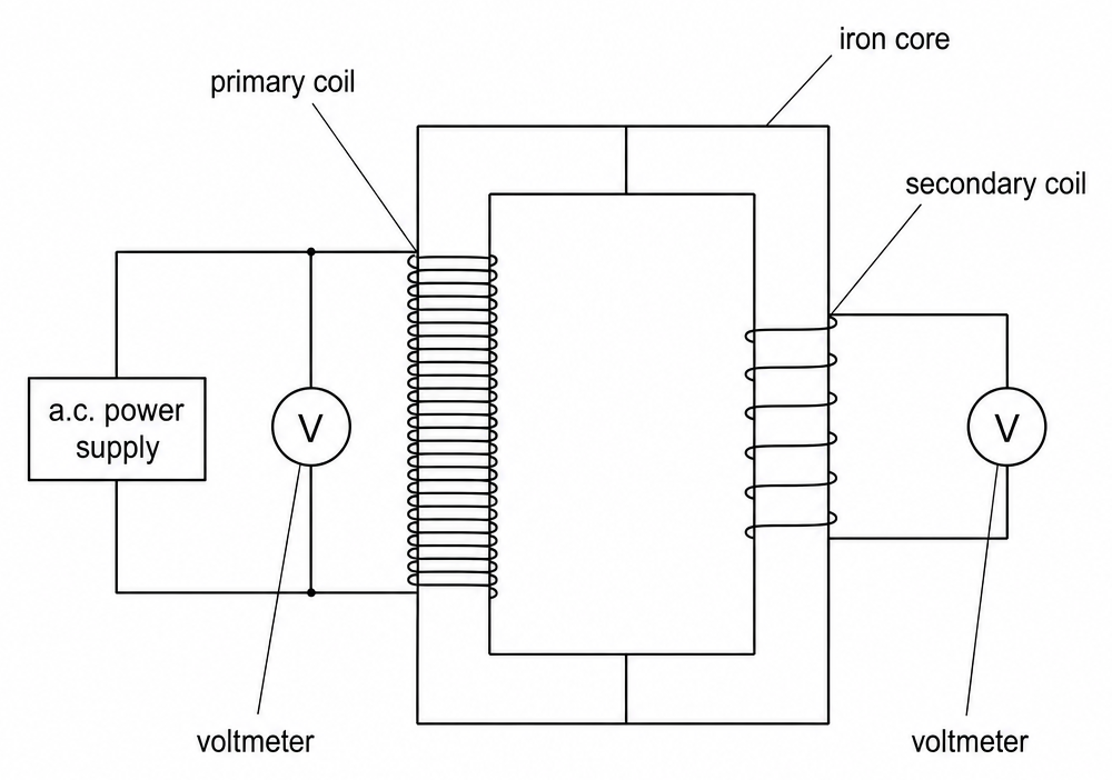
- A transformer has two coils of wire, the primary coil and the secondary coil, wound on a shared iron core.
- An alternating current in the primary coil makes a magnetic field that keeps changing direction. The iron core carries this changing field to the secondary coil, where it induces a potential difference.
- The field has to keep changing, so a transformer only works with alternating current.
- For a transformer that wastes no energy, the potential differences, , across the primary (p) and secondary (s) coils are in the same ratio as their numbers of turns, .
- More turns on the secondary coil than on the primary steps the potential difference up, and fewer turns steps it down.
- You can't measure the changing field in the core, but you can measure the potential difference it induces across the secondary coil.
- So in this practical you add turns to the secondary coil, measure its potential difference each time, and compare it with what the turns ratio predicts.
Variables
- Independent variable - The number of turns on the secondary coil.
- Dependent variable - The potential difference across the secondary coil.
- Control variables - The number of turns on the primary coil, the input potential difference, and the iron cores and how they're clamped.
Method
- Wind the primary coil - Wind 100 turns of flexible insulated wire round an iron C-core.
- Wind the secondary coil - Wind 20 turns round a second C-core.
- Clamp the cores together - So their flat ends meet and make a complete loop of iron.
- Connect the meters - Connect the primary coil to a low-voltage a.c. supply, and put a voltmeter across each coil. Both must be a.c. voltmeters, or multimeters on an a.c. range.
- Take readings - Switch on at about 3 V, and record the potential difference across each coil.
- Add turns - Switch off, add 20 turns to the secondary coil, and switch on again. Check the primary reading hasn't changed, and record the new secondary reading.
- Repeat up to about 100 turns - Then plot the secondary potential difference against the number of secondary turns, and draw a line of best fit.
Safety
- Hot coils - Keep the supply on a low setting, and switch it off between readings.
Worked example - Predicting transformer output
A student built a transformer with 100 turns on the primary coil and 60 turns on the secondary coil. The potential difference across the primary coil was 3.0 V, and the voltmeter across the secondary coil read 1.6 V.
Predict the output potential difference from the turns ratio, and explain why the measurement is different.
Step 1 - Write down the turns ratio equation
Step 2 - Rearrange for the secondary potential difference
Step 3 - Substitute and calculate
Step 4 - Compare with the measurement
The measured 1.6 V is 1.8 − 1.6 = 0.2 V below the prediction. As a percentage of the prediction, that's about 11%.
Step 5 - Explain the shortfall
- The turns ratio equation assumes no energy is wasted, but a real transformer wastes some.
- The coils heat up, because the wire has resistance.
- The iron core heats up as it's magnetised and demagnetised, and because of eddy currents.
- So less energy reaches the secondary coil, and its potential difference is a little lower than predicted.
Common exam questions
Question 1
A student sets both meters to a d.c. range and reads almost zero across both coils. Explain what has gone wrong.
An alternating potential difference is negative as often as it's positive, so its average is about zero, and a d.c. meter shows the average. The transformer is working, and the meters need switching to an a.c. range.
Question 2
A transformer has 50 turns on the primary coil and 400 turns on the secondary coil, with 12 V a.c. across the primary. Calculate the potential difference across the secondary coil, and say whether it's a step-up or a step-down transformer.
V. It's a step-up transformer, because the secondary coil has more turns than the primary.
Question 3
Why are the two iron C-cores clamped tightly together?
So the iron makes a complete loop with no air gap. A gap lets some of the magnetic field escape before it reaches the secondary coil, which lowers the output.
Question 4
What shape of graph do you expect for secondary potential difference against number of secondary turns, and what does it show?
A straight line through the origin. It shows the output potential difference is directly proportional to the number of secondary turns.
Question 5
How does laminating the iron core improve the efficiency?
The core is made of thin strips of iron with insulation between them. This reduces the currents induced in the iron itself, so less energy is wasted heating the core.